
Most of us have heard of Open Source Software, as in GNU Linux, but fewer of us have heard of Open Source Hardware (OSHW). If you haven’t, you have now, and I venture most Makers know the concept if not the term.
“Open source hardware is hardware whose design is made publicly available so that anyone can study, modify, distribute, make, and sell the design or hardware based on that design.”
- http://freedomdefined.org/OSHW
As Makers, most of what we do is open source. We study other’s projects, we build on what we learn, and then we document our project in order for someone else to do the same. Well, not all of us, but quite a few. It is sort of a “Circle of Life” kind of thing, and the freedom of this exchange is why I think the Maker movement is growing in leaps and bounds.
I wanted to document a project in a little different way than “step-by-step, this is how you build it”. I wanted to outline line how we used the Open Source Hardware idea to learn, create, and share a project of our own. Of course, if you want to build it, we’ll documented that as well, but here we will take you through the process we went through.
The Idea
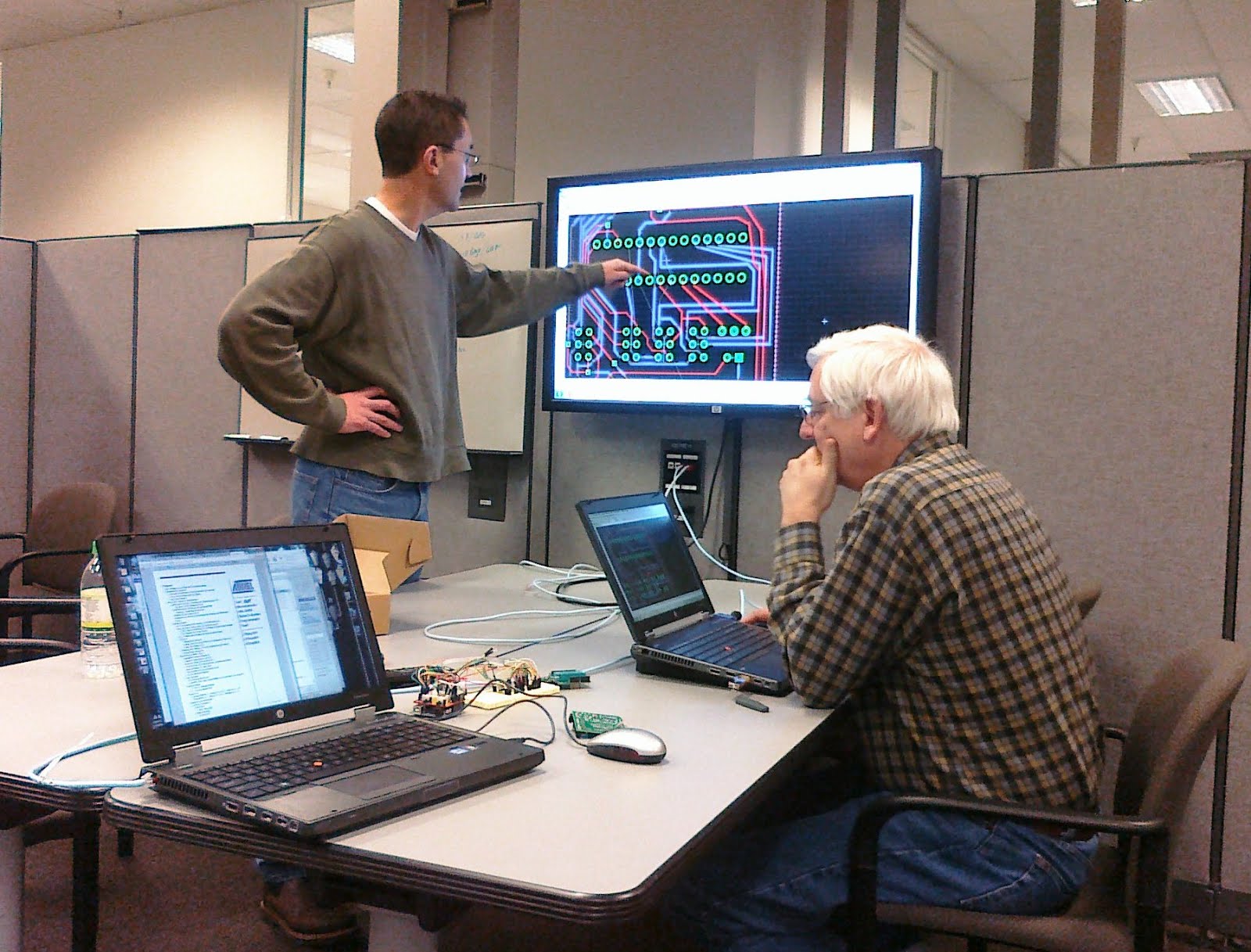
Our best ideas always seemed to be sparked by something we learn from someone else. At work, we have a group of people interested in embedded electronics who get together every other Friday to talk about what they've seen or done in the Maker world. The group spans from master Makers, who have produced and sold products, to novice Makers, who are looking to learn how to blink an LED. It is a great group to bounce ideas off, and for a while we had been looking for a project we could do together to learn circuit layout. One person had brought in an automatic mailbox light, showing how he programmed a BlinkM using the Arduino IDE. Another person had been wanting to transfer an Arduino project from the official board to a breadboard and was looking to burn a bootloader to a new chip. Both these projects can be done using the ArduinoISP sketch that comes with the IDE, but wiring it up every time you needed it seemed like a bit of an error-prone chore. Enter the AVR Programming Shield idea.
Learn
The best starting point for any project, after the initial idea, is to see what others have done. Turns out several hobby electronics companies have made shields for programming Atmega328 (Arduino’s main chip). These all use the ArduinoISP sketch and featured ZIF sockets for getting chips in and out easily. A separate software project extended the Arduino IDE to allow programming of Attiny chips like used in the BlinkM, and another project had made a small board for programming these smaller chips, but no one had put the two together in a simple manner.
We spent time studying each of the three main shield kits. They are all open source, and all provide schematics. Several also provided their PCB layout files as well. While they all use the same software (ArduinoISP sketch), and thus have roughly the same pin configurations, each had their own special tweaks. It was up to us to determine if we liked the feature and wanted to incorporate their ideas. Regardless if we used it, it was important to try and understand what they did and why. People are going to be looking at our plans later and asking the same question, “what were they thinking!” Hopefully, they’ll figure it out and say “that is kinda cool”.
So here was the goal for our group project: Create an Arduino shield that allowed for bootloading Atmega chips as well as programming the smaller Attiny chips using the ArduinoISP sketch. Piece of cake, right?
Try
The next phase of our research was to look at the pin layouts of each of the target chips and come up with a method to talk to each one. It turns out the pin assignments are vastly different for the different packages. The VCC pin on the attiny85, for example, matches the GND pin of the attiny84. We came up with three ideas for handling this problem. First, each chip could have it’s own socket. This would be simple, but require a lot of board space, and ZIF sockets are expensive. Secondly, you could use a single socket, aligning pin 1 the same every time, and then route signals using dip switches. This would require six switches (one for each ISP line), for each chip (18 total), and would still leave open the chance to mis-align the signals by having the wrong switches thrown. We found examples of projects using both these ideas, but weren't convinced that was the way to go. The third idea, and the one we went with, was to again have a single ZIF socket, but route the signals using a single jumper to one of three headers, one for each chip. There is still the possibility of using wrong header for the chip, but using a jumper also opened the possibility of using the ISP header to program a chip on it’s own board off the shield (say another Arduino with a new chip in it).
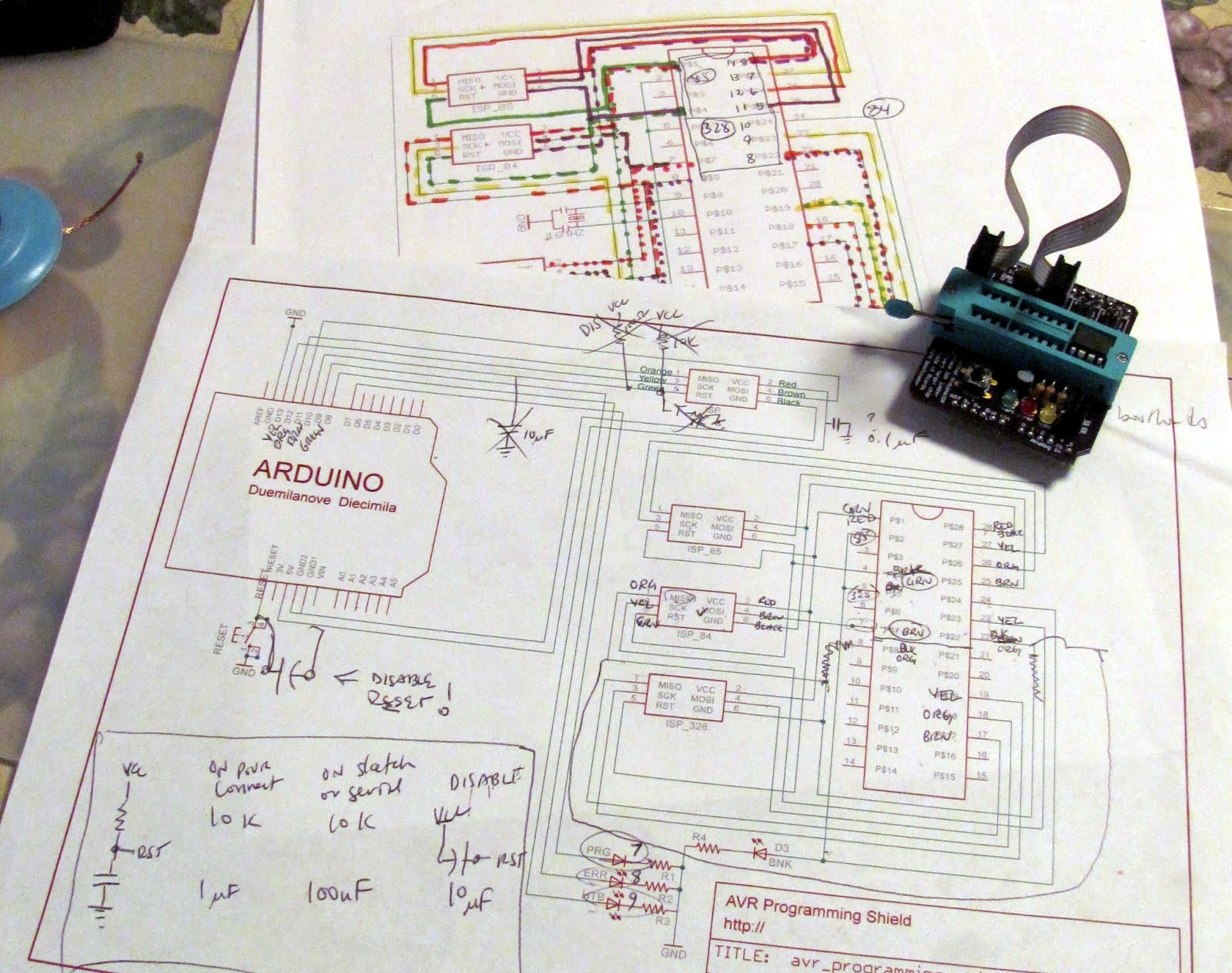
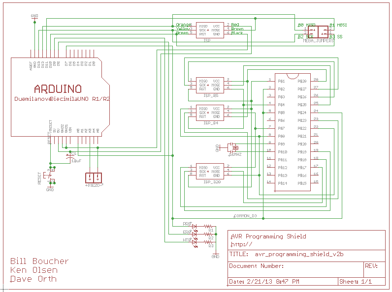
This all sounds good until you commit it to paper. Our next step was to draw out the circuit to see if this scheme was even viable. Since actually laying out a PCB was part of what we wanted to learn, we started by drawing the schematics in Eagle Cad.
Prototyping
Once we had a schematic that looked like it would work without releasing any magic smoke, it was time to try it out. It is always best to take baby steps, so a good first step was to start with the smallest chip, the Attiny85, put it on a breadboard, wire it up, and try and talk to it. This process would be repeated for each of the target chips until we had everything wired up and working.
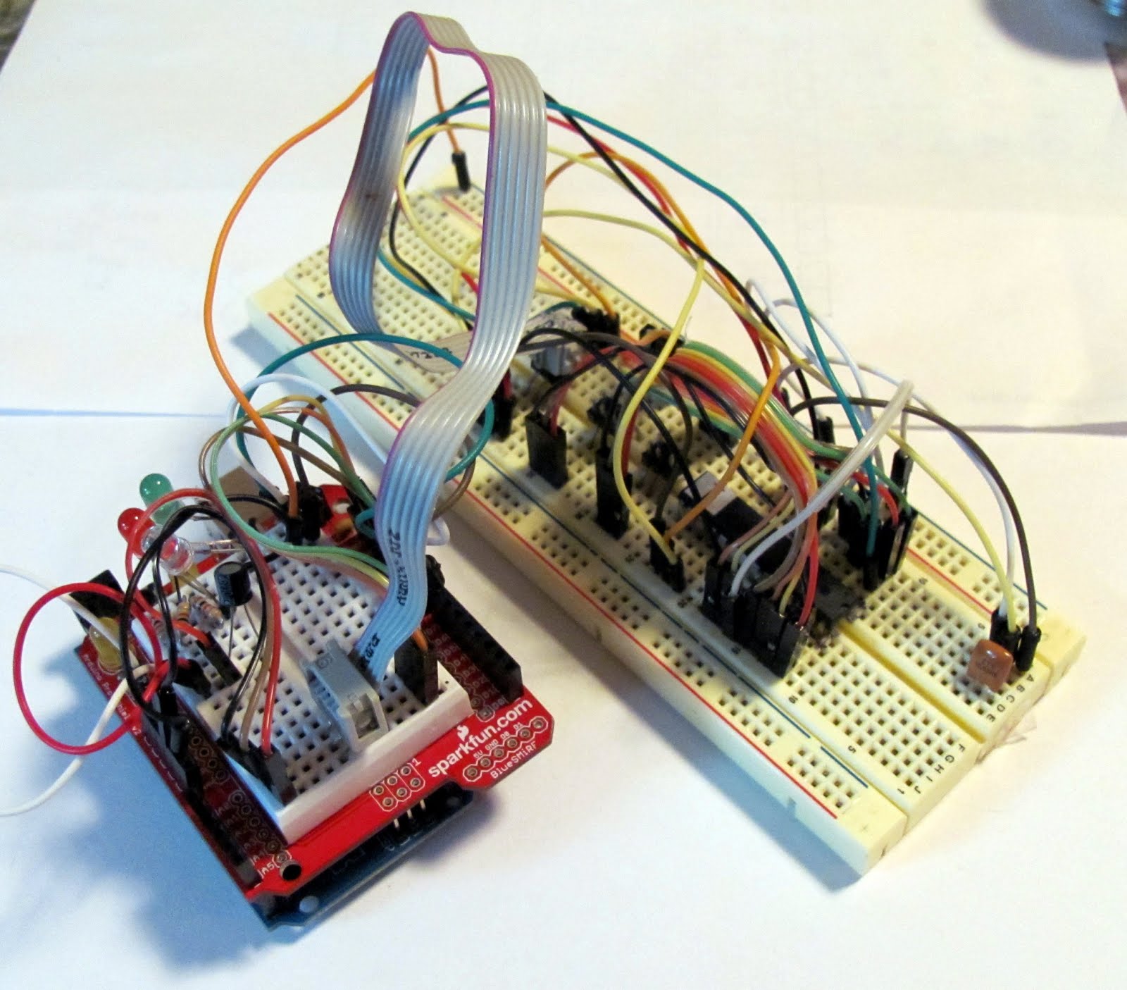
It sounds much easier than it was. We were plagued by such novice errors as jumper wires in the wrong spot and jumper headers put in 180 degrees out of position. Adding to the frustration was some sporadic behavior traced to breadboard rows being loose. We did have several things going for us. First, I had just bought a pack of new jumper wires, and was able to color code the ISP lines for the three sets of signal, making an impossible mess a little more manageable. Second, we only spent the lunch hour working on it, so would never get too frustrated at any given time and were always coming back to the problem with fresh eyes. And last, there were three of us, so careful watching and double checking caught a lot of errors before they became headaches.
Perhaps a final comforting thought was that all the headache we were working through would be spared, both for us when we used the shields, and for anyone else building the project. We were improving our skills in design and troubleshooting while lowering the bar for others who might try and follow our work.
One of the design features we added was the ability to have a programmed target chip blink an LED to confirm it was programmed. You know how Arduinoist love to blink LEDs. The problem is that the Attinys don’t have a digital pin 13 because they have fewer input/output pins. The challenge was to find a digital pin common to each chip that wasn't already being used for the ISP signals. Digital pin 3 became the candidate, allowing the default example Blink sketch to work by just changing the pin number.
Testing
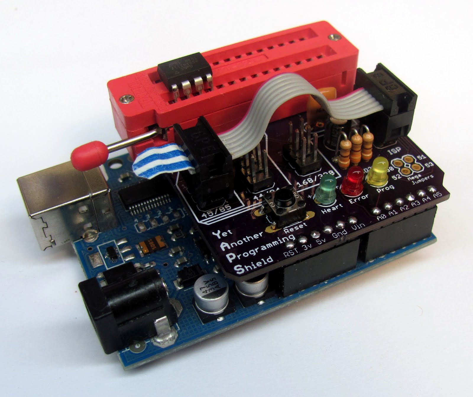
In addition to targeting the three chip families, we also wanted to make sure different Arduinos worked as the programmer. I contributed my trusty veteran Duemilanove for testing duties to join a fresh Uno. Additionally, we added the extra four jumpers that would be needed for an Arduino mega to use the shield (it’s ISP pins are on a different header), and tried that as well. A great part of being in a group of enthusiasts was the access to a wide variety of hardware.
A design issue that required addressing for using different Arduinos was the auto reset. When the Arduino IDE goes to upload code, it pull the reset line low to get the attention of the chip to be programmed which may be banging away on the last sketch you uploaded. (This also occurs in Windows when you open serial console, causing the sketch to restart). This feature become a liability when the Arduino in question is the programmer already running a sketch we need to pass on data to the target chip, and so for certain boards, needs to be disabled. We tested several methods, and ended up using a 10uF capacitor tied to power to keep the reset line high. This still allowed the reset button on both the Arduino and the shield to still function if needed, and worked for all board, even those that didn't really need it.
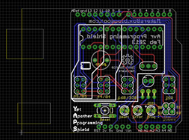
Layout
Once we were convinced that schematic worked as intended, it was time for the board layout. I don’t know how most people feel about it, but I think routing a layout it is an addictive multi-dimensional logic puzzle. You have two layers, top and bottom, to work with, and need to get the signals to the correct pins with as few crossovers, or vias, as possible. Your constraints are the size of the shield, which affects the cost, and the width and spacing of the traces. To your advantage are an auto-router function and the ability to move parts where ever they will fit.
Some things to remember:
- There are several great tutorials on the web to help. Start with SparkFun’s (https://www.sparkfun.com/tutorials/108).
- You are actually smarter than the autorouter, or will be after a little practice.
- Your experience with the schematic and breadboard setup should give you a feel for the most efficient way to route traces.
- There is a lot of trial and error involved.
- Smile, because even though you are frustrated, you are learning something new!
My experience with routing has let me to the following method:
- Place the parts logically based on what you know from the schematic and breadboard layout.
- Try the auto-router to see what it does and where it fails.
- Look at the unrouted traces to see where part placement or rotation may be beneficial.
- Rinse (undo) and repeat.
- Once the placement looks good, start with the most important signals like power and route them manually.
- Route any obviously symmetrical or repeating signals to your satisfaction. The auto-router will just spaghetti them without mercy.
- Load you board-house’s design rules first thing and check often. The further you get down the layout road, the more painful it gets to move things around.
- If you get stuck, save and let the auto-router have a crack at it.
- If you are really stuck, you either need more layout room (a bigger board) or better part placement. Rip it all up and start over.
Physical Layout
Once you have the board routed, it is time for a reality check. In hindsight, perhaps we should have done that prior to routing! We printed the board out at 1:1, taped it to a piece of cardboard, and use a thumbtack to “drill” holes. Once we placed the components, we could see what our project looked like in “user space”. In our case, the physical layout showed we needed to move a capacitor and bring the reset switch closer to the edge so my fat fingers could hit it reliably it. We decided we were O.K. with a little overhang on the ZIF socket since it was over the main board. Time to ship off the design files to a board manufacturer and wait. This was the time to order the parts we did not already have on hand during prototyping.
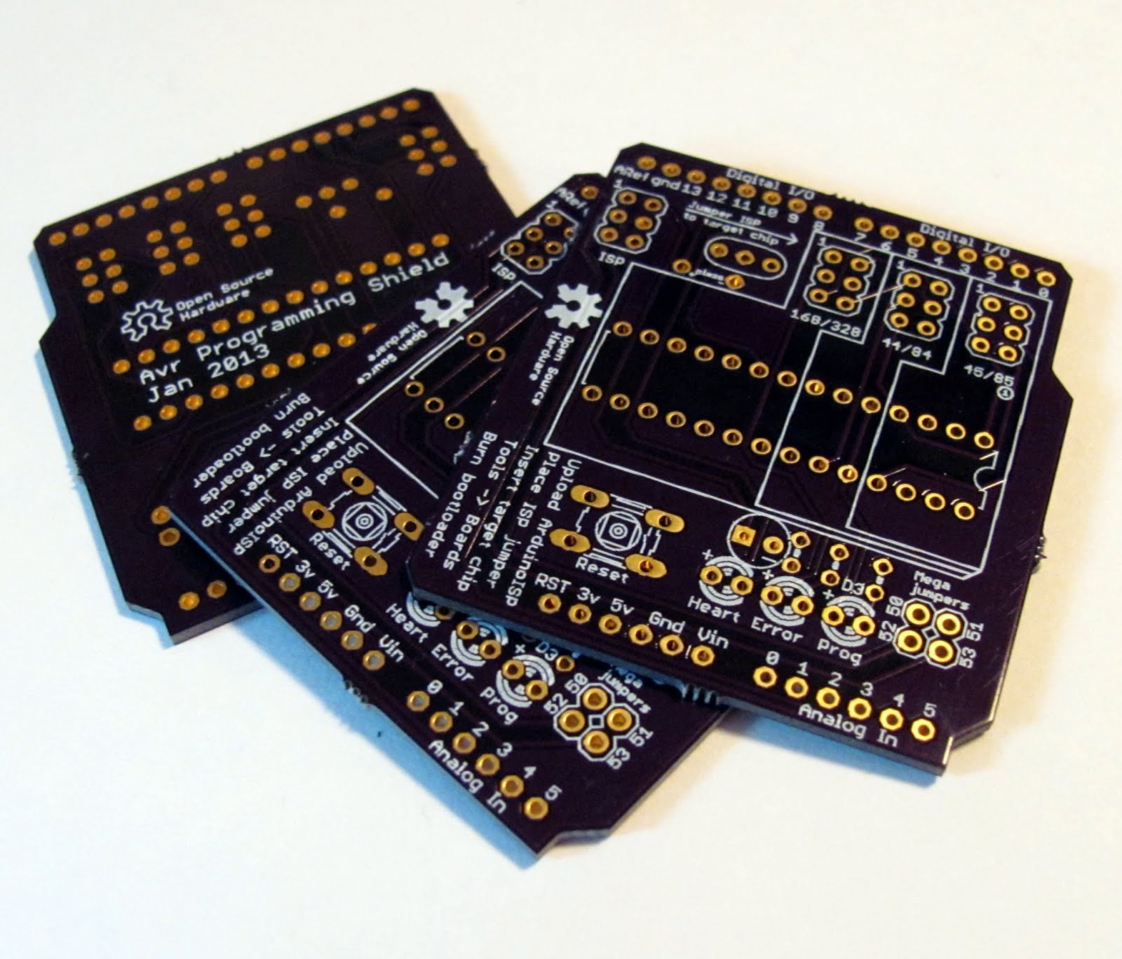
We used a company called OSH Park to manufacture the boards. They require a minimum order of three boards, which worked out perfect since there were three of us working on this. There was no setup fee, and shipping was included, so each board cost less than $7, which is an amazing bargain if you have ever tried to make your own. I have also used Sparkfun’s board-making service BatchPCB with great results.
Build
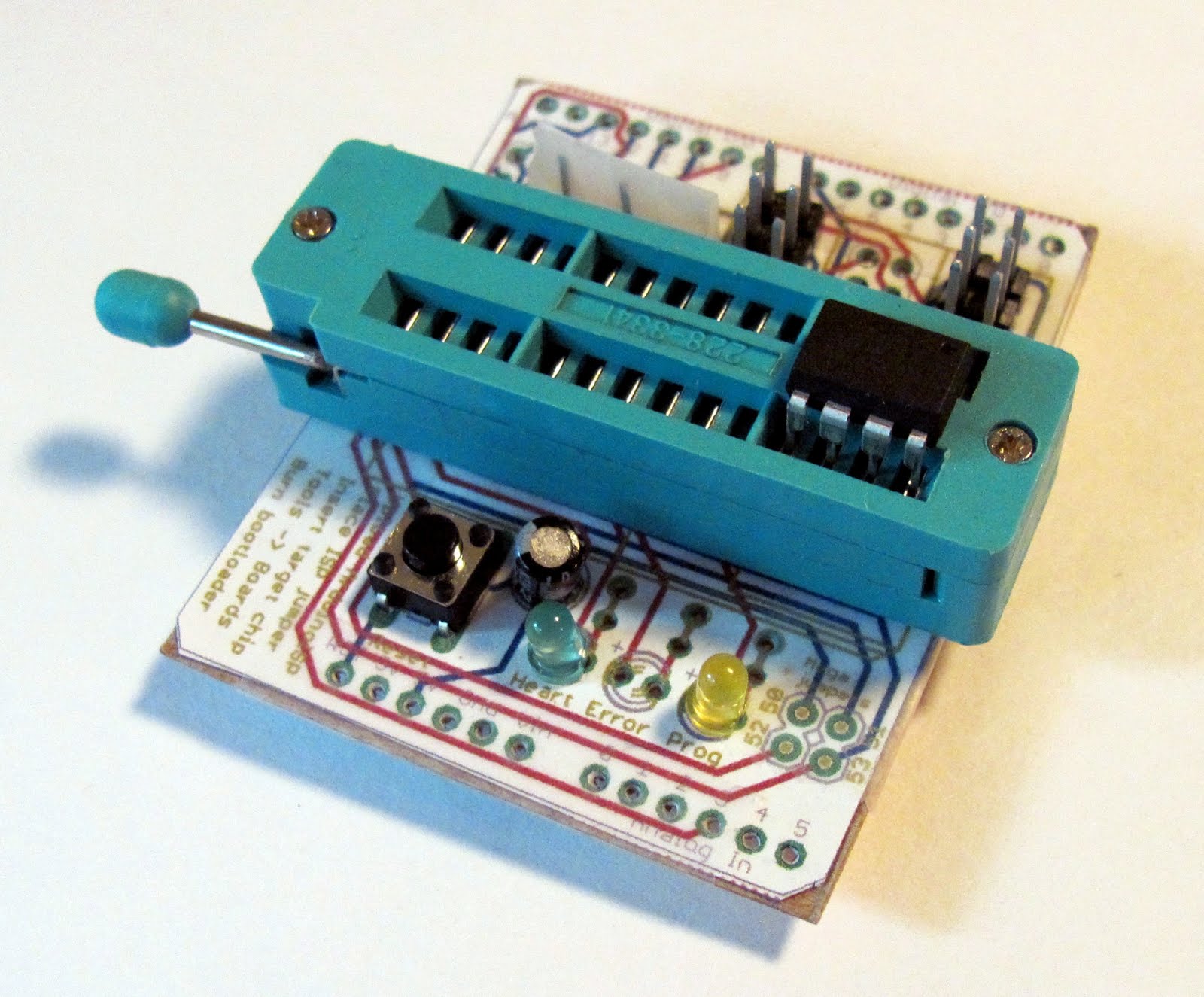
After all the effort that went into getting the breadboard version working, making the shield was a snap and took only a few minutes. All those loose wires vanish into two invisible layers on the board, and soldering make sure that the components don’t fall out every time you move it! Then it was just a matter of testing it on all the Arduino versions and using all the target chips. The only real design issue that surfaced was that the jumper headers were too close to the ZIF to make removing and inserting them easy. A small pull-tab of Tyvek solved that problem.
Share it with the word!
[You are here] It worked. We met our goals. It was fun learning, and we each had very nice programming boards to help with future Attiny projects. What now? In the spirit of open source, and being proud of our work, it was only natural to share what we had done with others.
My first attempt at an open source project five years ago, while generating a lot of interest, was very hard to replicate (see http://www.instructables.com/id/Buggy-A-Crafty-Programmable-LED-Creature/). I made the circuit boards by hand, and the chips required a dedicated programmer and a difficult to set up tool-chain. I know of only one other person who tried to replicate my work. Nowadays, the inexpensive and easy to use board manufactures like OSH Park take care of the circuit boards, and using the Arduino IDE and TinyCore libraries take care of the tool-chain. And as for the AVR programmer, well, we just made it!
The only way we could make this project any easier for someone to replicate is to make it into a kit. Parts come from several different places, which adds shipping costs. Buying parts in ones and two cost significantly more than in bulk. Buying three of a circuit boards doesn't help much when you are making just one for yourself. What if we put it all together in a kit? At the quantity of 50 kits, overall price of the components drops nearly 40%! Imagine at the scale of 1000s. No wonder they are able to do Raspberry Pis in lots of 100,000 at $35 each!
Unfortunately, the cost of putting 50 kits together is a bit of a barrier to us in the same way that having to pay for three boards might be a barrier to you. We have to sell a majority of the kits to keep from losing money, so it is a bit of a risk. Or is it? Just as design tools have gotten easier, and board-manufacturing cheaper, putting a small project like ours in to production has gotten a step up through new services like Tindie.com! We are able to put our design out there for pre-orders to see if there is enough demand to justify us spending the money and making the kits. That, perhaps, will be an article for another day.
Iterate
We copied a lot of people’s ideas and used a lot of people’s hard work. It is easy to forget that. Think of all the time and effort that goes into large open source projects like Arduino, let alone the smaller electronic projects that we studied. All these people were willing to share in the hopes that someone would take it farther. Now it is our turn. In addition to just making the kits available, we are posting our designs as well. Someone is going to learn something from them, even if it is just “how not to do it”, and perhaps make something even cooler. And hopefully, they’ll share it as well so we can see!
I am interested in the product so do you have a price for the kit plus postage to England or just the board price plus postage.
ReplyDeletebobwareham@gmail.com
Can you tell me the value for the resistors if I were to attempt a build myself. Total novice but seems like a doable project with boards from OSHPARK.
ReplyDeleteThanks.
I've got a kit ready to go for $25 (includes shipping), or I'll send you a board for $10. Send me an email.
DeleteIf you want to go ahead, the bill of materials is at http://oshpark.com/shared_projects/zDUTli76, where you can also order the PCB. It is a very straight-forward build.
I saw a video on Youtube showing your programmer. The person doing the video stated that you can program the ATTiny 2313/4313 but I don't see a ISP programming port for these chips on the board. Is this board also capable of programming the ATTiny2313/4313 ? If so, I am very interested in ordering a kit from you.
ReplyDeleteYou just use Attiny85 header. The pinouts (for programming) are the same except for the ground, so we've got it so it works for both chip families, but isn't labelled. Email me at 648.ken@gmail.com if you'd like to order one.
DeleteBought the kit for the price of the minimum order of un-populated boards, Very happy with quality and promptness of of the shipment, not to mention the savings on added costs I would have incurred to source the parts (and shipping) myself. Advice to anyone interested in a single working shield, just buy the kit and save yourself the hassle.. And it would support makersbox time and work in piecing it all together for us.
ReplyDelete