
An experienced hobbyist should be able to build a well designed project from the BOM (bill of materials) and the markings on the PCB. The rest of us need some help. I recently put together an $11 multimeter that had very little documentation, and I figured I might add some tidbits to the interwebs that might help others get through this. Like a Jedi and their lightsaber, what could be better than building your own instruments!

This is a DT-830T "Digital Multimeter Electronic Training Kit from Banggood.com. If by "training", they mean figuring things out on your own, this is a winner. My first plan of attack was to sort the resistors and mark the PCB diagram with values (why don't they do that to start with?) Ironically, since I can't identify anything other than 330, 1K and 10K by sight, I used a multimeter to test and label the resistors. Kind of a chick-and-egg thing. There are more 220K resistors than any other, so getting them out of the way significantly lowers the others than need sorting.
 The only thing that tripped me us was the fact that resistors R17 and R38 have switch position between the diagram and the PCB silk screen.
With resistors out of the way, I turned my attention to capacitors. Again, I'm not good with reading values, but another recent project, a GM328 Transistor Tester, got put to go use.

Here are the values and markings:
The final unidentified component was marked "4B DMZ". This is a re-settable thermal fuse, and by this point there are only a couple of empty spots on the PCB it could go (R32).
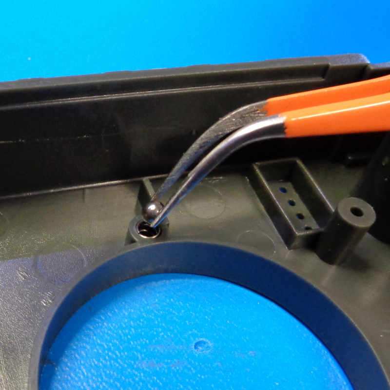
There are some springs and ball bearings that were not obvious (to me) where they went. I found a Youtube video of someone assembling this as a clue.

With everything assemble, it worked, and I tested it against known voltage and resistance, and it was pretty close. There is an a potentiometer (VR1), which I assume is for adjustment, so I tweaked it to match the known voltage.

My main use for a multimeter is as a continuity checker with the buzzer. That is where this meter shines. Instead of having to rotate the selector switch to the resistance setting on the Fluke and then press a button to get the speaker, I can leave the rotary on the DT-830T on continuity and just turn it on and off with the push button. Not many meters work that way. That alone makes it a keeper. Plus, I can say "I made this myself".
And, if it helps you, here is my scratchpad:


This is a DT-830T "Digital Multimeter Electronic Training Kit from Banggood.com. If by "training", they mean figuring things out on your own, this is a winner. My first plan of attack was to sort the resistors and mark the PCB diagram with values (why don't they do that to start with?) Ironically, since I can't identify anything other than 330, 1K and 10K by sight, I used a multimeter to test and label the resistors. Kind of a chick-and-egg thing. There are more 220K resistors than any other, so getting them out of the way significantly lowers the others than need sorting.

With resistors out of the way, I turned my attention to capacitors. Again, I'm not good with reading values, but another recent project, a GM328 Transistor Tester, got put to go use.

Here are the values and markings:
- C1 - 100 pF - "101"
- C7 - 220 pF - "221"
- C2, 4, ,5 ,6 - 100 nF - "104"
- C3 - 220 nF - "224"
- C8 - 1 uF - "105"
The final unidentified component was marked "4B DMZ". This is a re-settable thermal fuse, and by this point there are only a couple of empty spots on the PCB it could go (R32).
There are some springs and ball bearings that were not obvious (to me) where they went. I found a Youtube video of someone assembling this as a clue.
With everything assemble, it worked, and I tested it against known voltage and resistance, and it was pretty close. There is an a potentiometer (VR1), which I assume is for adjustment, so I tweaked it to match the known voltage.

My main use for a multimeter is as a continuity checker with the buzzer. That is where this meter shines. Instead of having to rotate the selector switch to the resistance setting on the Fluke and then press a button to get the speaker, I can leave the rotary on the DT-830T on continuity and just turn it on and off with the push button. Not many meters work that way. That alone makes it a keeper. Plus, I can say "I made this myself".
And, if it helps you, here is my scratchpad:

No comments:
Post a Comment